Mystery Machine wrote:WARNING:
This mod is VERY fiddly and should not be attempted unless you are CERTAIN you can do it! Read through the guide carefully first to make sure there is nothing beyond your capabilities……you could well end up with a messed up captains chair! :(
I do not accept any responsibility for any chairs that get messed up doing this – I am simply relaying my experience of doing a modification that I’ve always felt the Delica needs! :D
This job rates VERY highly on the Mystery Machine Profanity Scale!
To do the job you will need the following:
Endless amounts of patience
Lots of time to cool down between frustration bouts!
A VERY large swear box!
A good range of tools including:
Screwdrivers
Socket Set
Spanners
Angle Grinder
Workbench/clamp/vice
Files
A clean place to lay the seat while working on it – I laid out a picnic rug!
A willing volunteer to help with some parts (but I had to struggle on my own!!

)
First things first – if you are attempting the seat wobble cure – Mark’s instructions are excellent and this procedure can be carried out at pretty much anytime during the 90 degree mod.
Use Mark’s instructions
HERE to remove the seat and separate the base – although I found that removing the plastic trim around the seat base made separating the parts even easier:
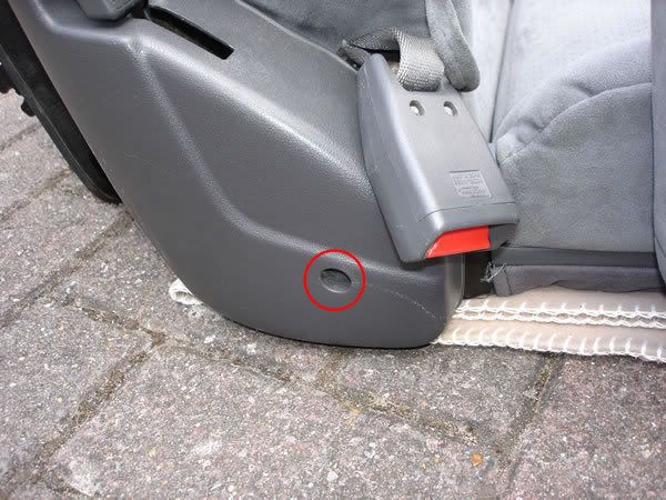
Remove this screw (
RED) and push the seatbelt buckle through into the seat base.

Undo the two trim screws at the front (
RED) and remove the trim (already removed in the photo)
Do the same for the side (
RED) and the back – not shown, but you get the idea!
 Now use Marks instructions to get the seat base seperated from the main body of the chair.......
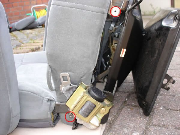
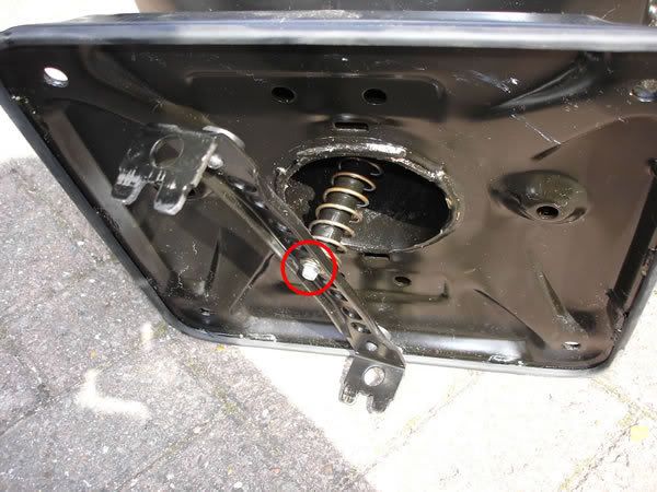
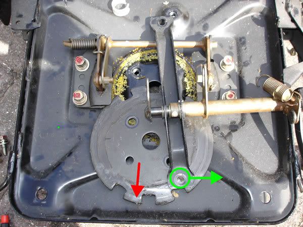
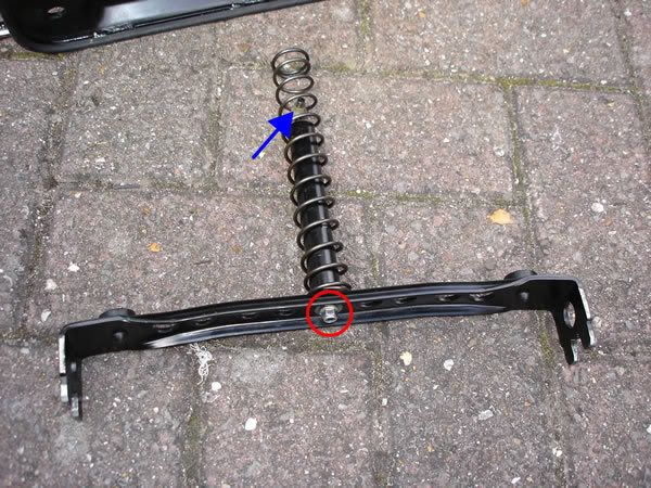
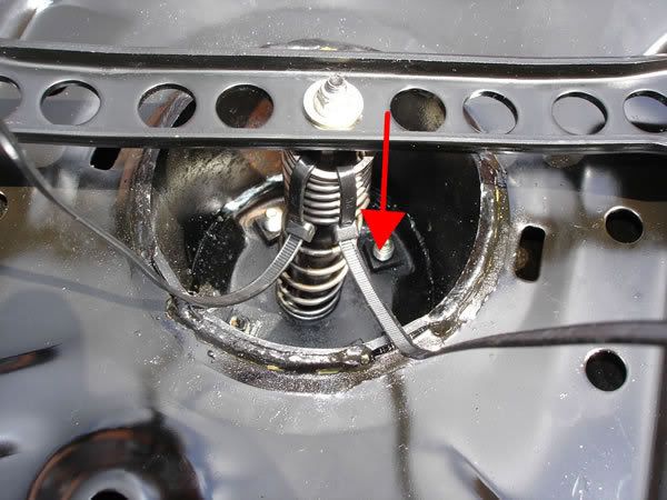
Now loosen the four bolts (
RED) with a 12mm spanner/socket. DO NOT REMOVE THEM – just undo them most of the way. (Now would be a good time to do the seat wobble mod.) Unclip the spring from its mounting clip (
GREEN CIRCLE)
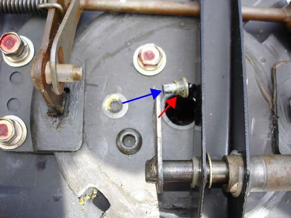
With the spring unclipped, slide the bar (
BLUE) to the left to release the arm from its locator (
RED)
Working underneath the seat base, use an 8mm socket/spanner to undo the nut (
RED) and remove the arm and spring. Be careful when doing this because the whole assembly is under a lot of tension from the spring! Make sure you don’t let any parts ping off!

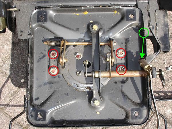
Once the arm and spring are removed you will be left with a bar coming down through the middle of the seat base (
RED) where the nut and washer were just attached (
GREEN)
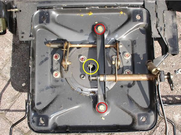
Back up on deck – undo and remove the two bolts (
RED) with a 12mm socket/spanner. The area circled in
YELLOW is the other end of the bar highlighted in
RED in the previous photo. This is where you’ll be working next…..

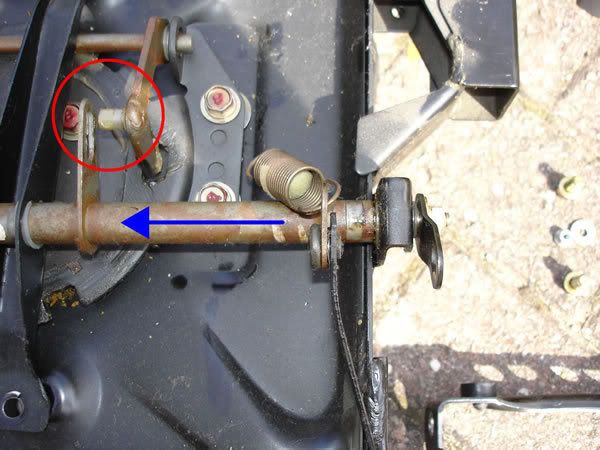
Using a pair of long nosed pliers, or a pair of small screwdrivers, lever of the small retaining washer (
BLUE) from the end of the bar (
RED) BE CAREFUL not to let the washer ping off into oblivion – you don’t want it ending up with all those lost odd socks etc….never to be found!!

:shock:
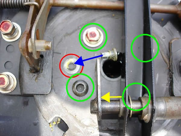
With the retaining washer (
RED) removed from the bar (
BLUE) now slide the main bar (
YELLOW) to release the arm from its locator.
Using a 12mm spanner/socket, undo and remove the four bolts (
GREEN) from the disc. You’ve probably noticed that the bottom left bolt is an allen key type – I can only assume this has been changed at some point for some obscure and unknown reason! You will probably have four bolts like the one top left??
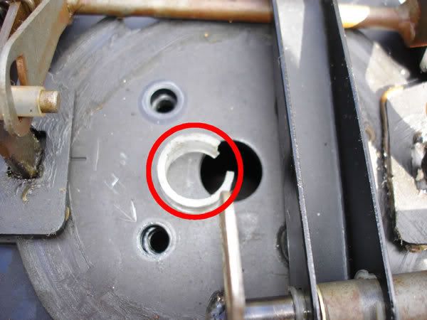
Carefully lever out the nylon washer from the disc (
RED)
Pulling the big bracket to one side (
GREEN) slide out the disc from the seat base (
RED) This is where you need to make sure the bolts on the clamps (the ones with the red paint on in the photo) are very loose!
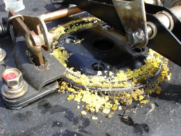
This mess is what I can only assume to be the remains of a nylon washer/bearing/support for the seat disc. Obviously it has worn away – probably causing the seat wobble! :? I decided to leave the mess because the nylon acts as a good lubrication for the disc. It might help and it certainly won’t do any harm to leave it!

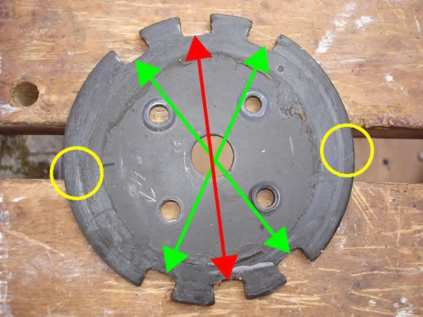
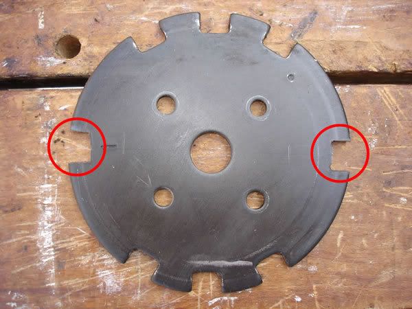
The disc removed – showing the slots for the chair positions:
RED for the forward an rear facing positions and the
GREEN for the 30 degree positions.
The
YELLOW circles show where the 90 degree slots will need to go.
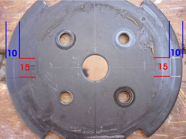
Note the centre lines I’ve marked through the disc….accuracy is all important here! The slots need to be 15mm wide (
RED) (7.5mm either side of the centre line) and 10mm deep from the edge of the disc (
BLUE)
Note that I also marked the bottom left hole with an arrow – this is to make sure I put the disc back in the correct way around!
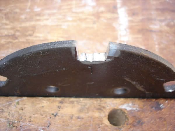
The slot cut out –I used an angle grinder, but a hacksaw ‘might’ do – just bear in mind that it is VERY thick metal and will take a lot of work!
Make sure you stay within your markings – it’s easier to remove material…..you can’t replace it (without a LOT of work and a welder!!

) I’ve still got a bit to remove on the left – and used a file to do this final bit.
If you do use an angle grinder – maybe best to cover up! It was a HOT day and I had no footwear or top on! OUCH!! : shock: I did have goggles on though!
The slots now cut (
RED) and finished off. Double and triple check your measurements before you refit the disc – once it’s in, it’s going to be a pain to remove again just because you didn’t get it right!

Replace the disc and refit and tighten all the bolts (
RED) with a 12mm socket/spanner.
Relocate the arm (
GREEN)
Make sure all nylon bearings/washers are properly located in their respective positions (
BLUE) – ESPECIALLY the one you removed from the centre of the disc!
Now for the fun/tricky bit!!
The next few photo’s caused me the most frustration – but having found a solution after LOTS of cussing and sore knuckles….I might have saved you some time and hassle!
Place the bar (
BLUE) through the spring and arm and put the 8mm nut & washer (
RED) on the bottom – but only do up by a few turns for now!
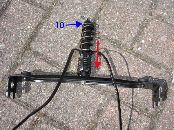
You need to fit the arm/spring back so that the end of the bar passes through the disc. This was impossible to do on my own due to the pressure of the spring and I had to come up with a means of doing it after countless attempts.
The best way I found was to use cable ties to compress the spring as much as possible(
RED) Wrap the tie around the spring – compress the spring as much as possible then tighten the cable tie. Compress the spring a little more, tighten the tie……do this bit by bit until the spring is compressed enough to allow AT LEAST 10mm of the bar (
BLUE) to protrude unhindered. 20mm would be better if you can compress the spring that far.
From the underside of the seat base – place the bar/arm/spring assembly back in the base (
RED) and ensure the wide tube passes neatly through the nylon washer in the disc.
The bar should now protrude through nylon washer in the centre of the disc. Replace the arm (
RED) and push on the retaining washer (
BLUE) as far is it will go.
From the underside of the seat base again – CAREFULLY cut the cable ties to allow the spring to re-tension. Push down on the arm when you do this to take up the tension, then cut the ties and release the arm slowly.
Now replace the spring on its locator (
GREEN) and ensure that all the bolts (
RED) are tightened.
Refit the seat parts in the reverse order using the guide that Mark produced (if you have already forgotten the sequence!!)
Put the seat back into the motor and bolt it back down – now test it out!!!! :D :D

 Call me BCDelica-less
 Good Ship