Right,
After
MUCH work trying to turn it into something you can actually make sense of from a really bad paper copy, I have finally cracked it!!
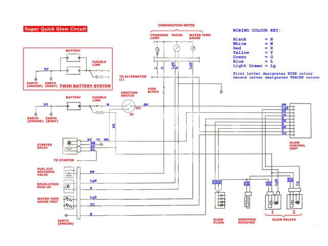
It's a bit too small to make out in this size, so
HERE is a better sized image of the
complete wiring diagram for the Super Quick Glow System :D :D
I have not put it up as a direct image link because might be a bit large for some monitors!

If you want a much bigger 2,500 x 2000 pixel version (just in case you want to print out in hi-res??) then
CLICK HERE 8) 8)
Hope that is a start??
I'll get to work on the other parts of the system when I get time! Maybe not today I'm afraid
(The next bits will be all the diagnostic checklists for every wire/pin in the main glow-plug circuit....

) I've digitized, edited and labelled all the drawings, it's just the 'fun' part of typing in all the data now!

Watch this space...... :lol:
Regards for now,
Bruce.
P.S. PLEASE NOTE - the 'IGI' shown in the diagram by the ignition switch should actually be 'IG1'!! This is more obvious when comparing the diagram to the diagnostic checklist that I will post up later....
It was a VERY poor copy of the wiring diagram and it was only when producing the dignostic list did I notice that it is a '1', not an 'I'!
Sorry about that!


 Call me BCDelica-less
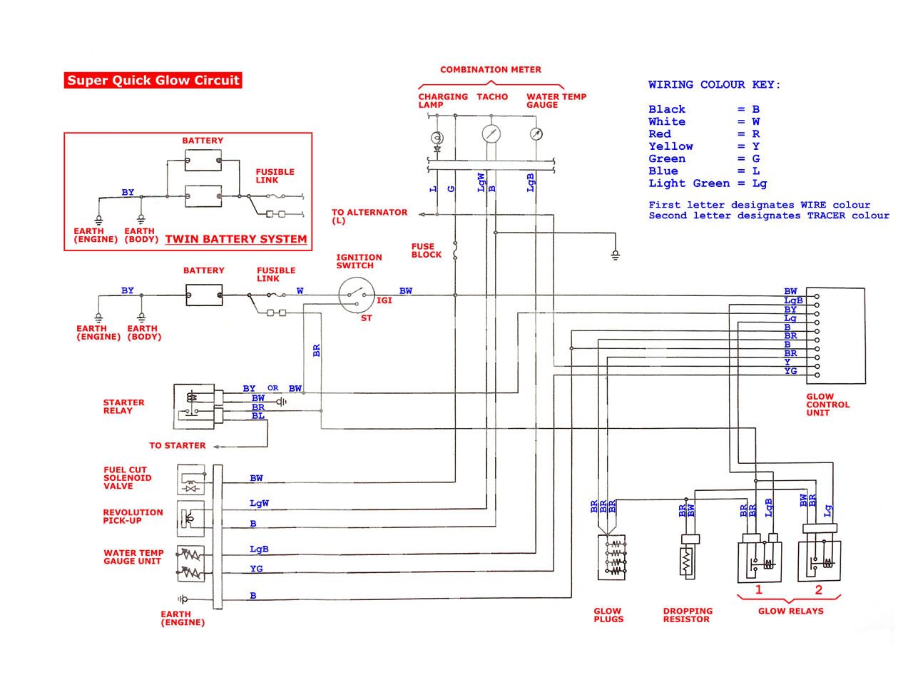